High-frequency behaviour
High-Frequency Propagation
How high-frequency energy behaves on cables and PCB tracks, and why wavelength, return paths and skin effect matter in audio systems.
Explore High-Frequency PropagationWhy electrical symmetry around earth matters — and why it is only the beginning of controlling high-frequency energy in an audio system.
A centre-tapped balanced transformer can present an audio system with two supply conductors that are equal and opposite relative to Protective Earth, while retaining the full 230 V differential supply between them.
Supply symmetry can reduce conversion of common-mode disturbance into differential error within connected equipment. Quiescent builds on this foundation by controlling the high-frequency paths through earth, chassis and the transformer environment.

In an ordinary supply, one conductor sits close to earth while the other carries the full supply voltage relative to it. A balanced transformer changes that geometry. Its centre-tapped secondary establishes two equal and opposite rails: approximately +115 V and −115 V with respect to Protective Earth, while the equipment still receives 230 V between the rails.
This matters because unwanted energy is often shared by both supply conductors relative to earth or chassis. When the supply is more symmetrical, there is less opportunity for that common-mode energy to be converted into a differential disturbance at an audio component’s power-supply input.
Illustrative principle
An audio system does not draw power as a perfectly steady load. As programme material becomes louder or more complex, its power supply asks for current in changing bursts. The transformer, the supply conductors, chassis and earth structure respond to that changing demand as a connected system.
Changing current demand alters conditions across the supply network. Quiescent investigates these interactions as part of the connected system: how programme-related demand affects the transformer, supply, chassis and earth environment while the equipment processes music.
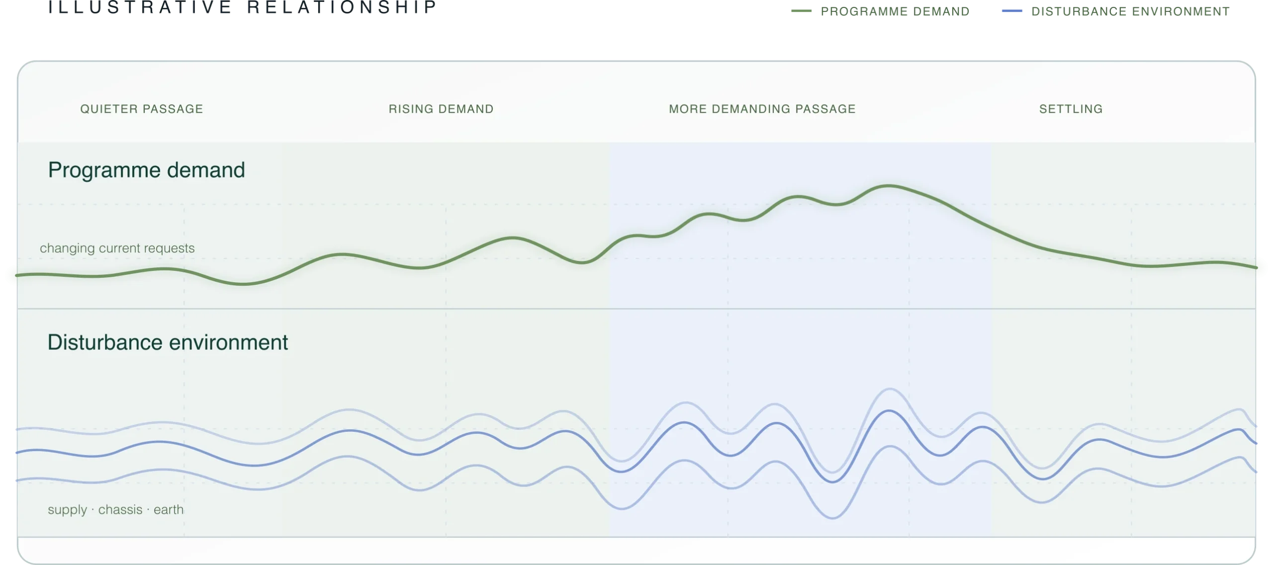
Illustrative relationship between programme demand and disturbance around the transformer, supply, chassis and earth. The traces explain the relationship rather than the measured levels.
The centre tap gives common-mode energy a route towards Protective Earth. That route is useful: it establishes the balanced reference and can carry some unwanted energy away from the two supply conductors. But at high frequencies, Protective Earth is not an ideal, zero-impedance destination.
Earth conductors, chassis bonds and connected ground structures behave as transmission paths at HF. Where a path changes impedance, branches, or ends without enough loss, part of the incident energy can be returned into the shared earth and chassis environment. In an audio system, that returning energy can remain available to interact with component references and signal-bearing circuitry.
Quiescent therefore keeps Protective Earth intact as the safety reference, while using Matrix absorption on the earth plane to provide a more controlled, less reflective destination for unwanted high-frequency energy. The aim is not simply to move HF noise into earth, but to reduce its ability to circulate through the common earth structure.
A transformer provides valuable isolation, but no physical transformer is ideal at every frequency. The primary and secondary windings are separated by insulation, geometry and often screening; they also form small parasitic capacitances. At mains frequency, those capacitances may be of little consequence. At higher frequencies, they can become a path for common-mode energy to couple across the isolation boundary.
Parasitic coupling is part of a practical transformer’s high-frequency behaviour. Quiescent uses Matrix absorption around the transformer and its associated earth and chassis paths to control residual energy reaching the secondary-side environment.
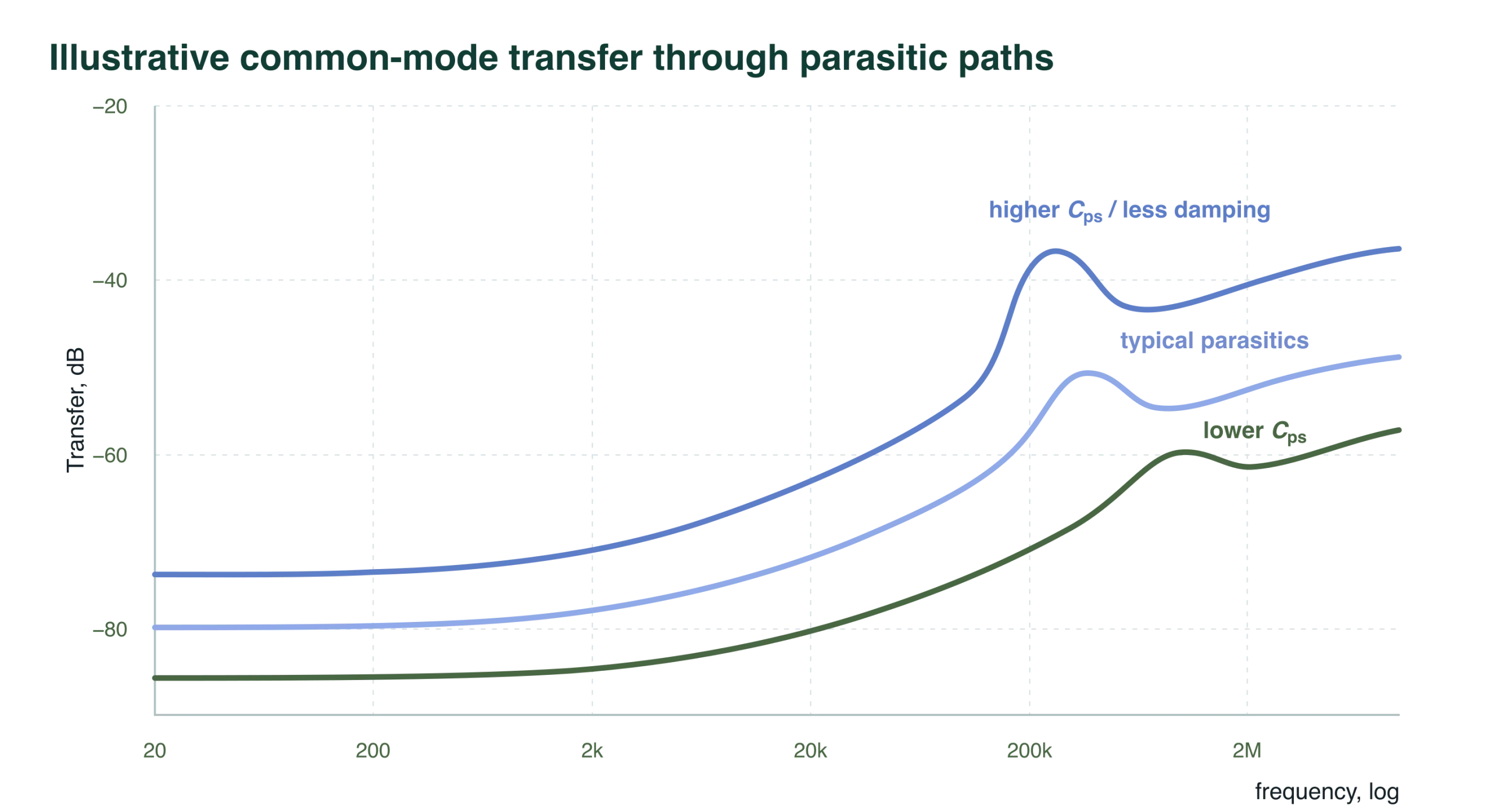
Lower primary-to-secondary capacitance and better damping reduce high-frequency transfer. Higher capacitance or a more reflective surrounding environment allows more energy to remain coupled across the boundary. The graphic illustrates high-frequency behaviour, not a specification for a particular transformer.
This graph illustrates the transformer’s transfer behaviour. The disturbance reaching the secondary depends on both that transfer behaviour and the high-frequency energy present at the primary.
The next view changes perspective. It shows the mixture of energy that can be present on Protective Earth: supply-frequency components, harmonics, switching-related clusters and wider RF activity. Together, the two views explain why Protective Earth is a path to understand, not simply a silent endpoint.
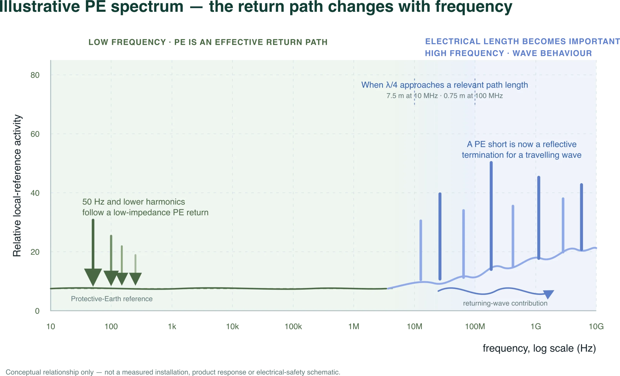
At lower frequencies, Protective Earth behaves as a low-impedance return path and harmonic voltage is held close to the reference. As the quarter wavelength approaches the length of a relevant cable, chassis or earth path, that route must be treated as a transmission structure. A short circuit at its far end is then reflective to a travelling wave, allowing high-frequency energy to return into the audio-system environment.
Balanced mains remains the foundation: isolation and symmetry make the relationship between supply, chassis and earth more controlled. The next question is what happens to the high-frequency energy that still follows the earth route or crosses the transformer through parasitic coupling.
If that energy is only blocked or redirected, it can meet another discontinuity and continue to reflect through the shared earth, chassis and supply environment. Quiescent adds deliberately controlled paths and Matrix absorption so that residual energy has a less disruptive destination.
Matrix absorption on the earth plane addresses the common-earth route. Matrix absorption around the transformer’s primary and secondary environment addresses energy that couples across the winding boundary. Together, these measures extend balanced mains from a useful transformer topology into a broader approach to unwanted energy within the audio system.
A centre-tapped transformer retains the differential supply while making the two rails equal and opposite relative to Protective Earth.
Protective Earth remains the safety reference. Matrix absorption helps reduce the opportunity for HF energy to remain active or return through the common earth structure.
Matrix absorption around the transformer environment addresses residual high-frequency energy that can couple across the winding boundary.
Balanced mains establishes a symmetrical supply reference. Quiescent extends that foundation by managing the remaining high-frequency routes through Protective Earth, parasitic winding capacitance and the surrounding transformer environment.
During our development and listening evaluations, reducing unwanted disturbance has repeatedly produced a clearer, more stable musical presentation.
These observations inform our systems approach to mains control. The relevant paths and the extent of the improvement depend on the connected equipment, supply conditions and installation.
Protective Earth must always be retained, and any mains product must be designed, installed and used in accordance with applicable local safety requirements. This page explains a systems principle; it is not a guide to altering mains wiring.
High-frequency behaviour
How high-frequency energy behaves on cables and PCB tracks, and why wavelength, return paths and skin effect matter in audio systems.
Explore High-Frequency PropagationSystem application
How two Matrix boundaries can define a quieter environment around a sensitive part of a system.
Explore Audio Subsystem ProtectionSystem application
Explore Quiescent’s approach to managing unwanted high-frequency energy across an audio system’s mains and earth environment.
Explore Audio Mains ControlThe diagrams illustrate supply symmetry, parasitic coupling and high-frequency return paths. They are conceptual explanations rather than measured product responses. Practical assessment considers transformer construction, connected impedances, disturbance spectrum and the installation’s supply, chassis and earth paths.
The references explain the underlying principles. Quiescent’s own research and development informs their application to working audio systems.