Foundation
The Physics of Quiet
The complete system view of unwanted energy, physical routes and controlled conditions.
ExploreTHE PHYSICS OF QUIET / 08
An electrical component is also a physical object, operating under changing force, field, temperature and stress.
Audio equipment is normally described through circuits, values and signal paths. Those remain essential. Yet the components that form those circuits also store and release energy, carry current, generate heat and experience mechanical force.
This page connects research on component behaviour with Quiescent’s investigation of working audio systems: how electrical excitation changes physical conditions, how those conditions affect circuit behaviour, and why controlling them matters to signal handling.
Voltage, current and magnetic field create real conditions within component materials. They can create electrical force, magnetic force, heating and mechanical stress. Movement, strain and temperature can in turn alter such quantities as capacitance, inductance, resistance, carrier mobility or magnetic loss.
This is not a metaphor. Research has modelled and measured these couplings in film power capacitors, toroidal magnetic cores, inductors, thick-film resistors and semiconductor structures. The construction, bias, excitation, mounting and frequency determine whether a mechanism is relevant in a given circuit.
Follow the relationship at your own pace.
Follow the relationship. Select Play guided explanation to reveal each step.
Illustrative coupling loop. Electrical excitation creates field, force and heat; changes in physical state can then alter an electrical parameter.
Magnetic components store and transfer energy through magnetic field. Magnetostriction, Maxwell forces and winding forces can excite structural modes. Core material, air gap, winding arrangement, clamping, chassis interface and damping all change the result.
Research on toroidal ferrite cores has linked magnetostrictive vibration, resonance behaviour and core loss under defined electrical conditions. Inductor research models both Maxwell and magnetostrictive forces and demonstrates the importance of geometry and resonance. These findings guide the assessment of magnetic components according to their material, construction, excitation and mounting.
Magnetic components are one example of the coupling between electrical and physical behaviour. The following illustration brings together four research-grounded mechanisms, each arising from a different component structure.
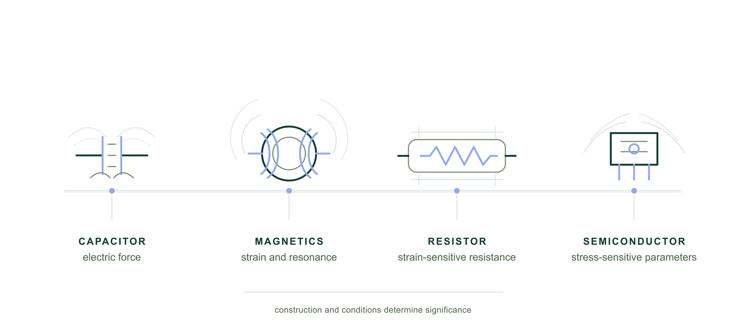
Research examples: film-capacitor electrical force and displacement; magnetic-component force and resonance; strain-sensitive resistive films; and stress-sensitive semiconductor parameters. The evidence applies to the specified materials and test conditions in each study.
The illustrations separate the mechanisms so each can be understood clearly. Their significance in a circuit depends on the component’s construction, operating point and physical environment.
In a real audio system, components do not operate in isolation. They share electrical supplies and return paths, physical mounting, thermal conditions and a changing electromagnetic environment. The conditions at one component can therefore be related to the operating conditions of another.
The useful question is not whether a component can respond to changing conditions—it can—but how those conditions are created, transmitted and returned through a connected system. The supply is a clear next example: it joins transformer, rectifier, reservoir capacitors, wiring and load in one time-varying network.
Rectification and reservoir charging create time-varying current demand through the transformer, wiring and capacitors. Those currents act within physical structures whose magnetic, mechanical and thermal behaviour depends on construction and operating conditions.
Programme demand is only one possible source of changing conditions. High-frequency disturbance, switching behaviour, mechanical coupling, thermal drift and connection behaviour can also form part of the environment in which components operate.
Loudspeakers, floors, equipment supports, chassis and cables provide routes for mechanical coupling. Identifying the contribution of each route requires assessment of the complete installation, including airborne excitation and transfer through floors, racks and connections.
Measurements of acceleration or velocity at the loudspeaker and electronics reveal how motion is transferred. Controlling cable position, support and tension helps distinguish cable-borne transfer from the other routes.
When changing programme or demand alters a state-dependent parameter, the resulting electrical error can follow the programme rather than behave as stationary random noise.
Its listening significance depends on magnitude, spectrum, timing, circuit position and the auditory cues affected. Hearing research helps interpret those changes; measurements and listening evaluations establish their significance in the working system.
Real components respond to their physical and electrical environment. Quiescent investigates the routes, forces and operating conditions that can create structured error, and develops ways to control unwanted disturbance across the connected system.
During our development and listening evaluations, reducing unwanted disturbance has repeatedly produced a clearer, more stable musical presentation.
These observations inform our engineering work. The relevant mechanisms and the extent of the improvement depend on component construction, circuit operation, mounting and the installation.
Return to the system foundation, explore why a changing error matters to music, or follow the high-frequency routes that form another part of the environment.
Foundation
The complete system view of unwanted energy, physical routes and controlled conditions.
ExploreSignal consequence
Why an error that follows changing programme conditions deserves attention.
ExploreHigh-frequency environment
How wavelength, surface current and return geometry shape unwanted high-frequency paths.
ExploreThe references document electrical and physical coupling in specified materials, component constructions and operating conditions. The illustrations explain those mechanisms rather than measured product responses. Quiescent’s own research and development informs their application to working audio systems.
The cited studies do not quantify the complete mechanical transfer from loudspeaker motion through a speaker cable into electronics, separately from airborne, floor and rack paths. Assessing that route requires installation-specific measurements.